
FT-6060J Fiber Laser Cutting Machine
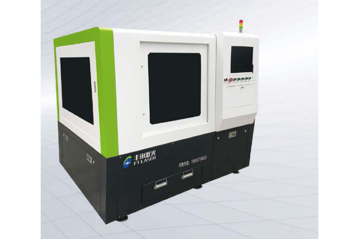
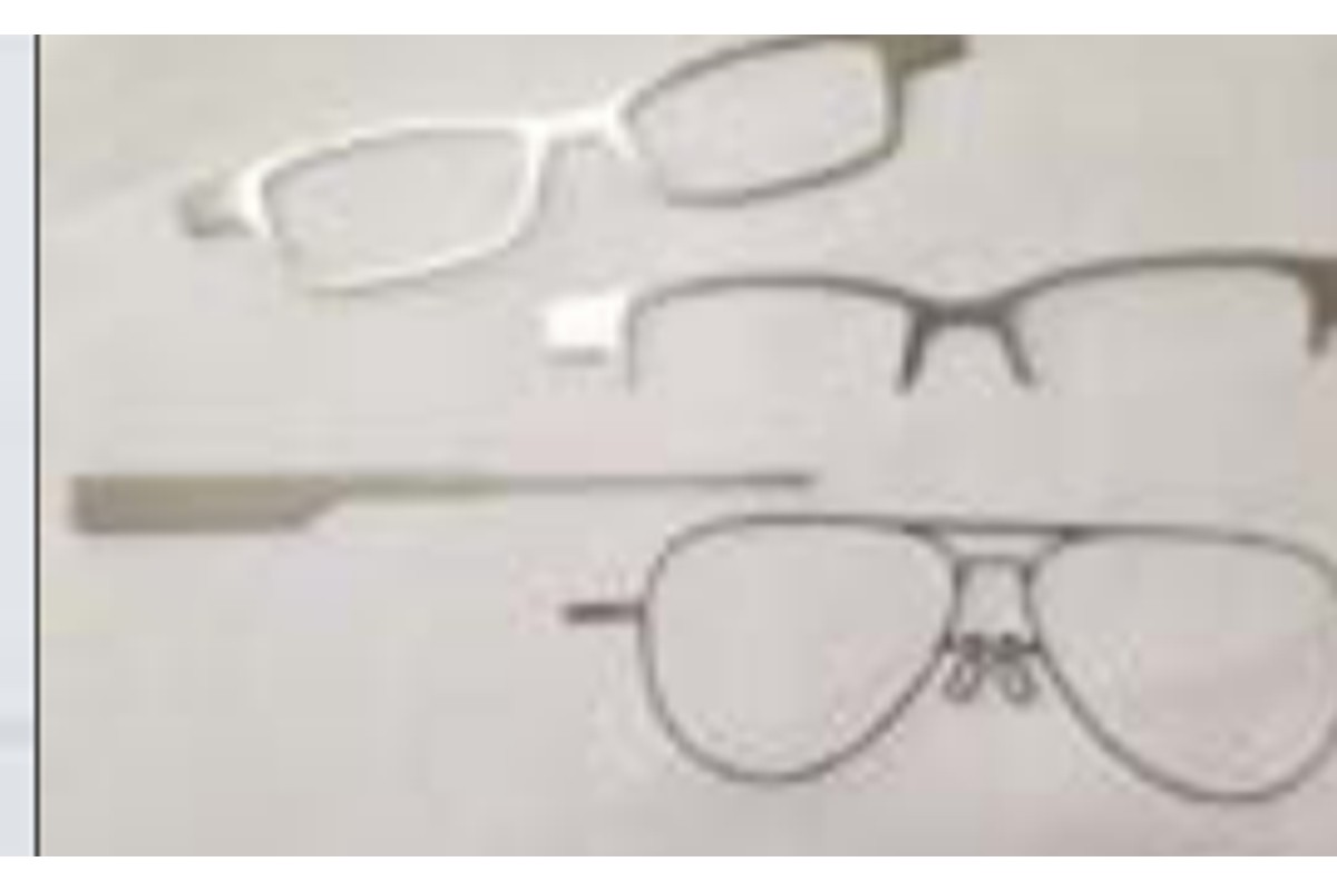
The FT-6060J is a compact enclosed fiber laser cutting machine presented in the catalogue for precision metal components. Its application examples include small decorative profiles and spectacle-frame parts. Select the configuration through a drawing review and inspected samples, especially when fine features determine acceptance.
| Product model | FT-6060J |
| Laser power options | 1500 / 2000 / 3000 / 6000 W |
| Catalogue X/Y positioning accuracy | ±0.02 mm |
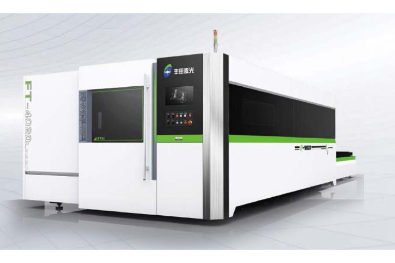
Images are taken from the product catalogue. Application examples illustrate possible component types; they are not sample-cut acceptance records.
Technical Specifications
| Product model | FT-6060J |
| Laser power options | 1500 / 2000 / 3000 / 6000 W |
| Catalogue X/Y positioning accuracy | ±0.02 mm |
| Listed overall dimensions | 1600 x 2100 x 1800 mm |
| Listed electrical supply | 380 V, 50-60 Hz |
| Working envelope | Confirm full X/Y travel; catalogue working-size entry states ≤600 mm |
| Processing focus | Small metal profiles and fine-feature component evaluation |
Specifications above follow the catalogue configuration. Final dimensions, component selection and utilities must match the confirmed order. Running speed is not a guaranteed cutting speed; positioning accuracy is not a blanket finished-part tolerance.
Precision Starts with the Part Drawing
The FT-6060J is aimed at a different purchasing question from a large sheet cutter: can the proposed process repeatedly make the small features that matter to this component? External profiles, narrow slots, small holes and thin ligaments can each require a different compromise between speed, heat and edge finish.
Begin with the drawing revision, material grade, thickness and critical dimensions. Identify features that are cosmetic and features that control fit. A decorative profile may tolerate a visible edge condition that is unacceptable on a locating slot. For spectacle-frame or other small-part projects, include the forming, polishing or assembly operations that follow cutting so the supplier can assess the complete requirement.
Confirm the Working Envelope Before Nesting
The catalogue gives the working-size entry as no more than 600 mm without a complete two-axis dimension. Obtain a dimensioned drawing confirming usable X and Y travel, clamping zones and the space needed for fixtures. Do not infer a 600 x 600 mm guaranteed cutting field from the model name or the single catalogue entry.
The listed overall machine dimensions are 1600 x 2100 x 1800 mm. These are not the complete installed footprint. Reserve room for access, maintenance, material placement, cooling and extraction equipment as required by the final configuration. Confirm package dimensions and lifting arrangements separately when planning delivery and installation.
Choose Laser Power Through a Fine-Feature Trial
The catalogue lists 1.5, 2, 3 and 6 kW laser options. More power does not automatically produce the most useful result on every small component. Ask for a trial that includes your narrowest slot, smallest important hole and the most heat-sensitive section of the drawing. Compare accepted parts and any finishing work needed after cutting.
Confirm the proposed cutting head, optics, focusing arrangement, control and process settings with the selected source. The material, thickness, gas, focus and motion through short segments influence the result. Avoid comparing only long straight-line cutting speed when most of the real program consists of short moves, corners and repeated piercing.
Kerf, Small Holes and Thin Ligaments
Kerf compensation should be established on the actual material and process. Measure both an outside profile and an internal opening: a change that improves one feature can affect the other. Keep a record of the accepted program and settings. Our kerf compensation guide for internal and external profiles explains why their corrections need separate attention.
A small hole is not defined by diameter alone. The ratio between hole diameter and material thickness, piercing method, geometry and quality requirement also matters. Review our practical guide to minimum laser-cut hole diameter before agreeing on sample features. Where a drawing requires a tighter fit or surface than the laser process can demonstrate, retain the necessary secondary machining operation.
Workholding and Part Collection
Small parts need support during cutting and a reliable collection method after release. Ask how the fixture or support surface prevents movement without obstructing the path. Review whether microjoints or another retention method are needed for your part. Any retained connection adds a later removal or finishing step and should be included in the route.
Inspect thin or flexible parts for distortion after cooling and handling. The first acceptable sample does not establish repeatability across an entire batch. Use the intended support and collection method during the trial, and check whether surface marking, scratches or manual removal affect the result. Agree on packaging or separation needs if completed parts can damage one another.
Measure Finished Parts with an Agreed Method
The catalogue positioning figure of ±0.02 mm describes the machine specification. It is not an unconditional tolerance guarantee for every completed part. Define datums, measurement conditions, instrument capability and the acceptance drawing before the demonstration. Measure the features that control fit rather than selecting only easy dimensions.
Where repeatability matters, inspect samples from more than one position and at different points in a representative run. Check edge condition, burr, discoloration and distortion as well as dimensions. Retain the material lot information, program revision and process record. This helps your quality team distinguish a process change from a variation in sheet condition.
Production Cost and Routine Care
Estimate cost using accepted components per complete cycle. Include sheet preparation, fixture setup, loading, piercing, cutting, removal, finishing and inspection. On a fine-feature job, setup and inspection can be significant even when the machine motion is fast. Evaluate these tasks before projecting daily output.
Ask for the electrical demand of the selected machine and auxiliary equipment, gas requirements, cooling conditions and extraction specification. Obtain the maintenance schedule and initial consumables list. Protective-window cleanliness, nozzle condition and a stable process setup matter when a small change in the cut affects the fit of a miniature component.
Frequently Asked Questions
Is the machine suitable for every precision component?
No universal suitability follows from the name. Submit the actual drawing, material and tolerance for a sample review, including required downstream operations.
Does the enclosure establish a certified clean process?
No. Confirm laser-area protection, extraction and the applicable documentation for the installation. Product-specific cleanliness or industry approvals require separate evidence.
Can a catalogue kerf value be used directly in a production drawing?
Use a measured, approved process value for the selected material and setup. Validate both internal and external features before freezing the program.
Request an FT-6060J Sample Review
Send a dimensioned drawing and part file through our precision laser cutting machine enquiry page. Include material grade, thickness, critical tolerances, edge and surface requirements, batch size and the intended next operation. Ask for a confirmed working envelope, matched configuration and documented sample trial so the purchase is based on inspected parts.