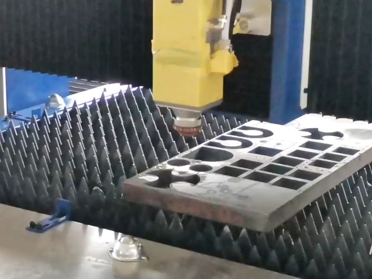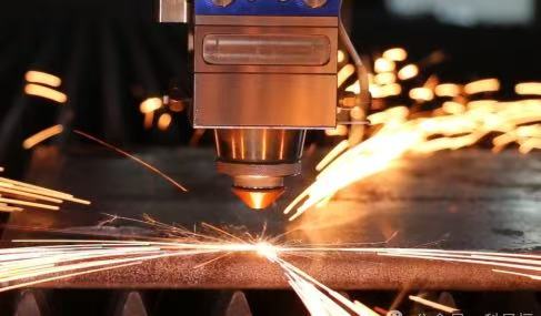
Laser cutting kerf compensation shifts the programmed toolpath to account for the width of metal removed by the beam. With no compensation, a centered cut can leave an outside profile undersized and a hole oversized. To correct both, measure a sample cut, confirm how your software defines the offset, and check that the finished dimensions hold on a production part.
How Do You Measure Laser Kerf on Sheet Metal?
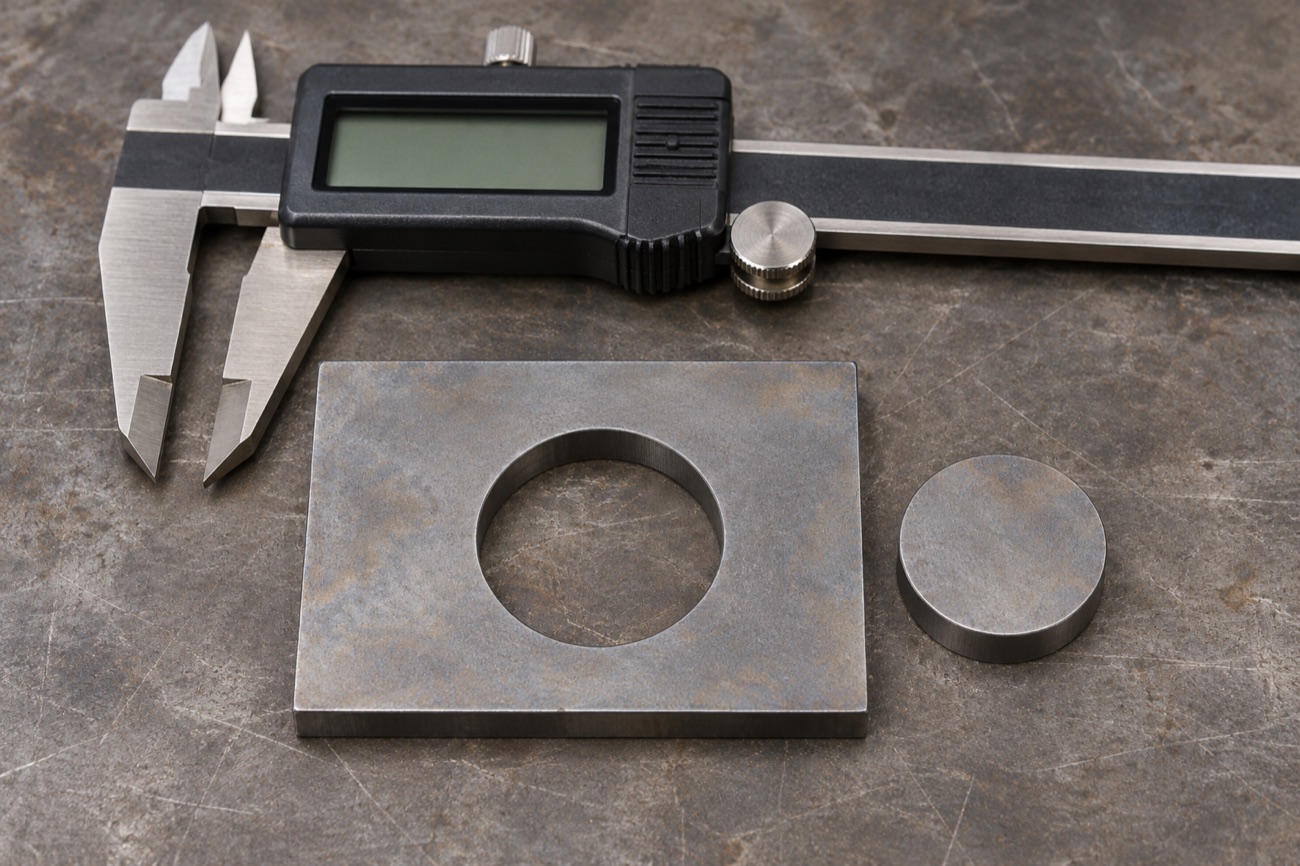
Cut a circular opening and retain its matching round slug. Use the production material grade, thickness, assist gas, and cut recipe. For a baseline test, use a sufficiently large circle with compensation disabled on the test job. Mark the top face before removing the parts. Once they cool, measure the opening and slug across the same direction and at corresponding faces, avoiding the lead-in and visible dross. Repeat in a second direction and on several coupons.
For an approximately symmetrical cut, estimate kerf by subtracting the slug diameter from the opening diameter and dividing by two. For example, an opening of 20.18 mm and a slug of 19.82 mm give an estimated kerf of 0.18 mm. The 0.36 mm difference spans the cut on both sides of the circle. Use an inspection tool suited to the drawing tolerance, especially for small holes.
Should You Enter the Full Kerf or Half the Kerf?
A measured 0.18 mm kerf corresponds to a geometric centerline shift of 0.09 mm per edge. The shift goes outward on the outside profile and inward on the hole, in each case toward the scrap. If the software asks for full kerf width, enter 0.18 mm for this example. If it asks for the offset per side, enter 0.09 mm. Confirm the field definition and inspect the toolpath preview before cutting.
Apply compensation in one place in the workflow. If the nesting program has already shifted the toolpath, an additional controller offset can double the correction. Check that closed contours are classified correctly, particularly when a part has internal cutouts or nested geometry.
What Do the Hole and Outside Dimensions Tell You?
Hole large and outside profile small. Insufficient compensation is one possibility. Verify the toolpath and compare the size error with the measured kerf. A 30.00 mm outside width measuring 29.90 mm and a 10.00 mm hole measuring 10.10 mm would be consistent with an uncompensated 0.10 mm kerf under simplified geometry.
Hole small and outside profile large. Check for excessive or duplicated compensation. Confirm the drawing dimensions and the settings in both the nesting software and the controller.
Both dimensions wrong in the same direction. Check drawing scale, units, measurement method and actual cut geometry before changing the global offset. If only small holes fail, compare their diameter in two directions and inspect the entry point. A single global offset cannot correct ovality or a localized mark.
Why Does the Same Hole Measure Differently on Each Face?
If the top and bottom measurements differ, the cut wall may be tapered. A fixed offset shifts the entire contour but cannot make tapered walls parallel. Confirm which face the drawing or inspection plan specifies, then review focal position and cut conditions. Use the guide to laser cutting quality parameters to narrow down what to check. If deposits interfere with the reading, inspect the edge with the dross troubleshooting guide.
When Should You Recheck Kerf Compensation?
Recheck when the material grade, sheet thickness, assist gas or cutting recipe changes, or when measurements begin to drift. Keep a record of the recipe, gas, measured kerf, software input and inspection face. Verify the smallest relevant opening and a critical outside dimension on an actual nested part before using the setting for the lot.
What Should Buyers Request in a Machine Trial?
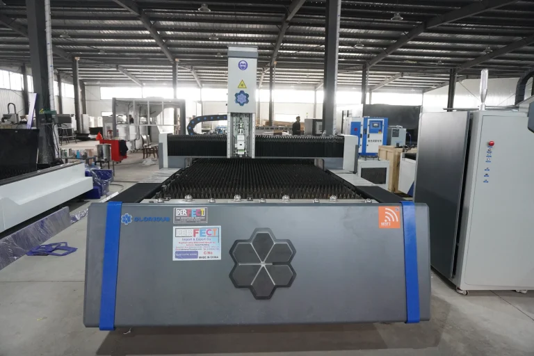
When comparing a sheet metal fiber laser cutting machine, send the actual material specification and a representative drawing. Mark the critical hole diameters, outside dimensions and allowable tolerances. Ask for several samples from the same nest, measurements by feature and face where relevant, and the cut recipe used. This gives you a way to compare repeatability and decide whether a part can go directly to assembly or needs a secondary operation.