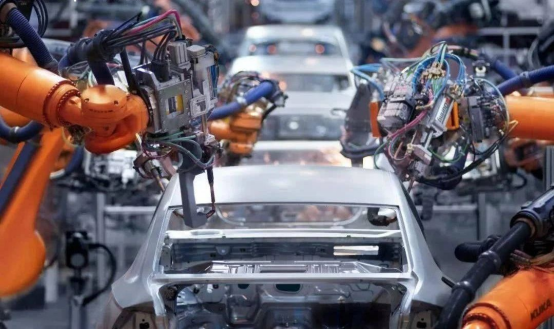
The automotive industry is constantly striving to improve product performance and fuel efficiency by reducing vehicle weight. The recent use of aluminum-based structures in this industry has led to the development of aluminum space frame structures (assembled from castings and profiles), aluminum alloy panel assemblies (based on steel monocoque structures), and the use of lightweight materials for castings.
Laser welding has potential applications in all these areas. For space frame structures where joints may require complex operations, Nd:YAG lasers with fiber optic beam delivery are often used.
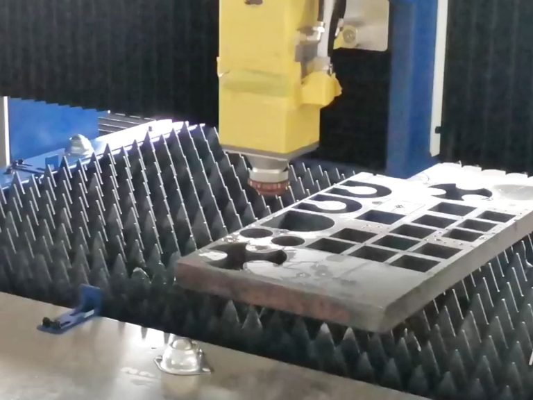
For aluminum alloy sheet assemblies, laser welding of butt-welded sheets (where flat plates are butt-welded together to form a part) will reduce the number of stamping operations required, the amount of different materials (e.g., 5000 to 6000 series) and thicknesses (to reduce weight) to be joined, and scrapping (to save on the cost of aluminum alloys).
While the welding of steel has been thoroughly studied and well documented, aluminum alloys have proven more difficult to weld reliably. Porosity, heat-affected zone (HAZ) cracking, porosity formation, and failure to weld through are all frequently encountered problems in aluminum laser welding. This paper discusses a study designed to help address some of these challenges.
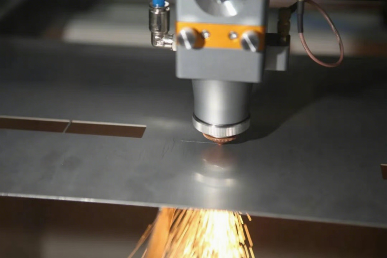
The YAG laser welding experimental setup
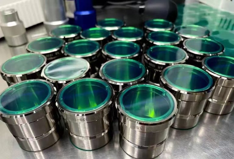
was used to conduct a study involving the welding of aluminum billets on the edge of a standard guillotine using a 4 kW continuous wave Nd:YAG laser equipped with a 600 µm fiber. 5000 and 6000 series aluminum alloy plates ranging from 1.6 to 2.0 mm thick were evaluated (see Figure 1). In addition, a number of filler wires were used to control weld metal composition details, increase joint gap tolerances, and improve top or root welds by eliminating undercuts (also shown in Figure 1).
| Material Composition (wt %) and Properties | |||||||||||
|---|---|---|---|---|---|---|---|---|---|---|---|
| Alloy | Form | Temper | Si | Fe | Cu | Mn | Mg | Cr | Zn | UTS (N/mm²) | Elongation |
| 5053 | Sheet | H3 | 0.20 | 0.20 | 0.05 | 0.23 | 1.46 | 0.06 | 0.02 | 291 | 16.6 |
| 6081 | Sheet | 0 | 0.06 | 0.32 | 0.01 | 0.82 | 4.85 | 0.01 | 0.01 | 217 | 9.5 |
| 6082 | Sheet | T6 | 0.83 | 0.48 | 0.03 | 0.44 | 0.80 | 0.03 | 0.02 | 307 | 13.9 |
| 4043 | Wire | — | 4.85 | 0.36 | 0.01 | 0.01 | 0.01 | — | 0.01 | — | — |
| 5556A | Wire | — | 0.08 | 0.34 | — | 0.37 | 5.60 | 0.07 | — | — | — |
Standardized process parameters (welding speed, joint gap, wire feed rate, etc.) were developed. Metallurgical analyses, tensile tests and press molding were performed to determine the quality of the welds.
The average power generated on the workpiece by the self and wire feed welding was 3.50 kW. The wire feeding equipment feeds the wire into a planetary head with a wire straightening device for easier positioning in the weld seam. The wire is guided through a copper conduit to the wire feed nozzle, which is mounted on an adjustable bracket attached to the focusing head. Helium gas is used for top and bottom weld channel shielding.
Wire Feed Process in YAG Laser Welding
Joint gap size, wire size, and weld speed are used to define the nominal wire feed speed using the following equation:
Wire Feed Speed = Welding Speed X Gap Area / Filler Wire Area
Wire feed speed and welding speed are measured in meters per minute, while gap area and filler wire area are measured in square millimeters.
The results show that successful filler wire feeding is dependent on the wire feed delivery angle and position in relation to the laser beam and weld area. Angles between 30 and 60 degrees were attempted, but the best result was 45 degrees from vertical.
The location where the filler wire meets the molten pool is probably the most important setting for smooth transfer of the wire feed into the molten pool. The wire must not intersect the laser beam above the molten pool as this will result in excessive spatter, tool damage and reduced depth of fusion.
In these welding tests, the optimum cross position for the laser beam was approximately 1.5 mm in front of the molten pool. The laser beam/wire crossover position was set at a 45-degree angle to the plate surface, 1.5 mm from where the laser beam meets the workpiece.
When welding with filler wires, gas protection of the molten pool is important, especially if there is a gap between the plates to be joined. In this case, it is more important than marking of the self-fusion weld because the molten pool is much larger than the self-fusion laser welding keyhole.
The helium flow settings were chosen from previous work. A flow rate of 10 liters per minute was used in the wire feed nozzle and 40 liters per minute in the coaxial nozzle. These flow rates provide the most consistent melt depth and visual weld quality.
Weld Speed, Material Preparation
There are some differences in weldability between the 5000 and 6000 series alloys. For a given spot size (0.60 mm) and power density (1.2 X 10⁶ watts/minute squared), the 5000 series material (with magnesium) appears to weld faster than the 6000 series material (with magnesium-silicon). One possible reason for this is that evaporation of the magnesium contained in the alloy during the lock-hole welding process results in a more stable lock-hole.
| Welding Speeds of Aluminum Sheet Alloys With and Without Filler Wire | |||||
|---|---|---|---|---|---|
| Material | Welding Condition | ||||
| Alloy (Thickness) | Filler Wire | Spot Size (mm) | Weld Speed (m/min.) | Wire Feed Speed (m/min.) | Gap (mm) |
| 5083 (1.6mm+1.6mm) | — | 0.60 | 11 | — | 0 |
| 5083 (2.0mm+2.0mm) | — | 0.60 | 8 | — | 0 |
| 5083 (1.6mm+2.0mm) | — | 0.60 | 8 | — | 0 |
| 5083 (1.6mm+1.6mm) | 5556A | 0.60 | 11 | 4.7 | 0.30 |
| 5083 (1.6mm+2.0mm) | 5556A | 0.60 | 8 | 3.4 | 0.30 |
| 6082 (2.0mm+2.0mm) | — | 0.60 | 7 | — | 0 |
| 6082 (1.6mm+1.6mm) | — | 0.60 | 10 | — | 0 |
| 6082 (1.6mm+2.0mm) | — | 0.60 | 6 | — | 0 |
| 6082 (1.6mm+1.6mm) | 4043 | 0.60 | 10 | 4.2 | 0.30 |
| 6082 (1.6mm+2.0mm) | 4043 | 0.60 | 6 | 2.55 | 0.30 |
| 5083 + 6082 (1.6mm+1.6mm) | — | 0.60 | 10 | — | — |
At this stage, magnesium content appears to be a dominant factor, and it was not possible to verify the influence of other alloying elements (e.g., silicon, iron, manganese, etc.) in this work. However, laser welding of 5000 series aluminum alloys requires close control of the undercut protection layer to achieve a smooth weld channel with no material dropout under the weld channel. The complete results are summarized in Figure 2.
Typical welding speeds were 8 to 11 meters per minute for 5083 alloy and 6 to 10 meters per minute for 6082 alloy. The addition of filler wire material improved not only the weld profile, but also the tolerance of the gap between the plates. For various plate thicknesses (1.6 to 2.0 mm), a wire feed speed of 2.55 meters per minute can accommodate seam gaps of up to 0.30 mm. When the wire feed speed is increased to 5 meters per minute, gaps of 0.5 mm can be closed.
YAG Laser Welding Material Preparation
In terms of material preparation, the Nd:YAG laser welding process appears to be able to produce consistent welds on aluminum alloys under received conditions (without the need to remove the oxide layer prior to welding). However, the presence of an oxide layer that may contain moisture may affect the level of porosity in the weld. This may in turn affect the mechanical properties of the joint.
In addition, in some cases, welds must be made with pressure lubricants/oils or with special surface treatments. The effect of these factors on weld performance and weld properties was not examined in this study.
Porosity
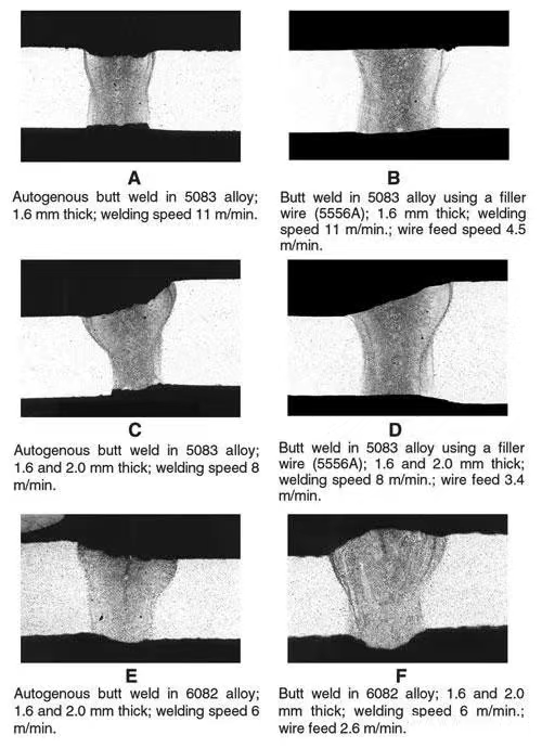
Porosity occurs in three forms: through-thickness porosity, large irregular pores, and small spherical pores. In these weld tests, porosity levels were evaluated by radiography. For autogenous welds, porosity levels were very low for both 5000 and 6000 series aluminum alloys.
Typically, there were less than five porosities less than 0.5 mm in diameter in a 100 mm long weld of 1.6 mm thick material, but there was no discernible pattern discernible for different alloys or different filler types. Welding results were very similar with the addition of wire (see Figure 3).
Porosity occurs in three different forms – thickness pores, large irregular pores and small spherical pores.
The reduction in porosity can be attributed to two main factors:
- increased average power (and power density) at the workpiece. The increased power density at the workpiece maintains a stable keyhole during the welding process. The small holes remain open during the welding process and the solidification time increases, allowing gas holes to escape on both sides of the weld.
- Improved gas shielding setup with coaxial helium shielding under the top weld bead and helium weld bead.
Mechanical Properties
The properties of laser welded seams, with or without filler, were evaluated by tensile and formability testing. Formability evaluations are particularly important for the potential use of aluminum in spliced panel applications.
The Erichsen cupping test, in which a 20-mm-diameter ball is pressed into a sheet and the height of the dome before failure is measured, was used to measure formability in this work.
The hardness distribution across the weld was measured using the Vickers pyramid indentation method. A load of 0.1 kg was used during the measurements.
In general, laser welded non-heat treatable and heat treatable alloys exhibit different mechanical properties.
5000 Series Alloys (Aluminum-Magnesium Alloys). 5251 Aluminum alloy produced an average tensile strength of 92% of the base metal and an elongation at break of 4% from self-laser welding. The addition of 5% magnesium (5556A) filler wire did not significantly improve these values.
For 5083 aluminum alloy, the average tensile strength of the self-welded seam was 96% of the base metal value and the elongation at break was 9.8%. The addition of 5% magnesium filler material increased the average tensile strength to 98% of the base metal value, the elongation to failure was 12%, and failure occurred in the base metal/HAZ.
Tensile tests on different thickness combinations (1.6 to 2.0 mm) showed that the fracture occurred in the base metal of the thinner plate in the weld. The average tensile strength of the autogenous weld was 94% of the base material value and the elongation at break was 9%. The addition of filler material resulted in a slight increase in tensile strength and elongation, with failure occurring in the thin (1.6 mm) material away from the weld.
In these solid solution strengthened alloys, the reduction in tensile strength is caused by the loss of work hardening in the weld metal due to porosity or undercutting and the reduction in effective cross-sectional area. Losses of alloying elements such as magnesium in the range of 5% to 10% have also been reported to reduce the tensile strength of the weld metal.1 The heat-affected zone is also annealed during the welding process.
The addition of filler wire material not only improves the mechanical properties but also leads to fracture of the base metal/heat affected zone.
In addition, filler wire strengthens the weld zone by eliminating undercutting at the top weld or at the root of the weld. The complete results are summarized in Figure 4.
6000 series alloys (aluminum-magnesium-silicon). For these heat-treatable alloys, welds tested in the as-welded condition showed an increased loss of tensile strength and elongation compared to the 5000 series alloys. The reduction in weld tensile strength of precipitation-hardened alloys is caused by redissolution and/or strain hardening of the precipitates in the weld metal. The heat affected zone is also softened by excessive aging during welding. The hardness results show a 25% reduction in hardness values compared to the base metal [Vickers hardness (Hv) 150 for the base metal, Hv113 for the HAZ and Hv110 for the weld metal].
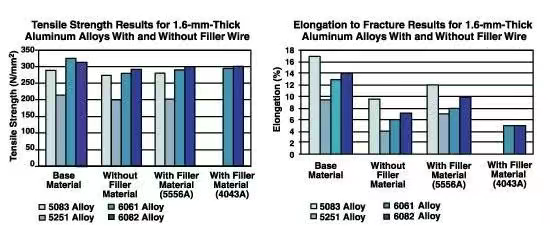
The tensile breaking strength of 1.6-mm-thick 6082 aluminum alloy typically ranged from 85% to 90% of the base metal strength for autogenous and wire-fed welds (with AlSi 4043A and AlMg 5556A fillers), with elongation failures of 4% to 12%. Welds made with 4043A wire have lower elongation at break values than 5556A wire.
Formability
An Erichsen cupping test (20 mm diameter mold) was also performed to determine the post-weld formability of the laser weld samples. Welded samples were tested at the root of the weld in the direction of the punch. The test results showed a similar trend to the elongation at break values from the tensile tests.
Failure heights ranged from 9.34 to 12 millimeters for the 5000 series alloys and from 8.30 to 9.7 millimeters for the 6000 series alloys. For specimens welded without filler material, fracture occurred at the weld seam; in welds with added wire, failure occurred in the base metal. The results are comparable for similar and different thickness combinations.
Failures occurring away from the weld region indicate that the base material failure requirements for welded steel plates are close to being met in laser welding of aluminum alloys. These improvements were achieved by increasing the welding wire, the weld profile, the power density of the workpiece, the welding and wire speeds, and the thermal cycle. Additional improvements to the process can be made by further optimizing these parameters.
YAG Laser Welding
As shown in this study, the increased average workpiece power provided by a 4 kW continuous wave Nd:YAG laser source can be used for spliced plate welding of aluminum alloys, which is less dependent on surface preparation than conventional welding.
As discussed, some of the tensile test failures occurred away from the weld region, suggesting that the parent material failure requirements for sheet steel spliced welds are close to being met in laser welding of aluminum alloys. This improvement was achieved by using filler material in these weld tests and optimizing laser and process parameters. Further work is planned to fully characterize and develop the laser welding of aluminum alloys with wire filler materials.