In modern manufacturing, laser cutting technology is widely used due to its high precision and efficiency. However, issues like low material utilization and thermal deformation during processing often lead to increased production costs. This article explores how design optimization can effectively reduce these costs.
1.Design affects the utilization rate of sheet metal, reduce production cost through design
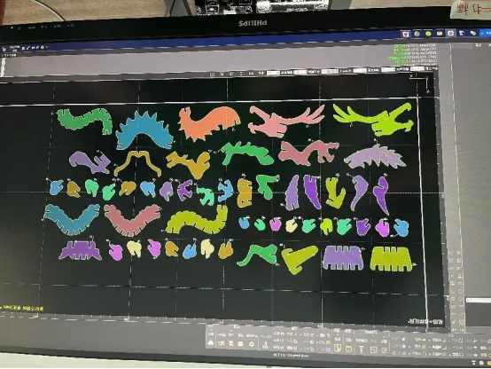
Generally speaking, after we get the 3D drawings, we will convert the workpiece into sheet metal parts and expand them into 2D drawings, and then after the nesting software, the parts of the same material and plate thickness will be nested and nested on the same plate.

Similar to this layout above, when well-designed and tightly laid out, the sheet can be maximized, resulting in less waste.
And this workpiece, with its various shapes, will inevitably lead to a large amount of scrap production in the middle.
Therefore, how to reduce production costs from the design is a point we need to spend time to think about.
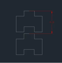
Please see the figure below, due to the workpiece can not be nested, can only be separated from the layout, resulting in a lot of material wasted between the two workpieces, and we only need to not affect the use of the workpiece under the premise of a slight modification of the design of the workpiece, you can significantly improve the utilization of the plate, reduce the material costs of production!
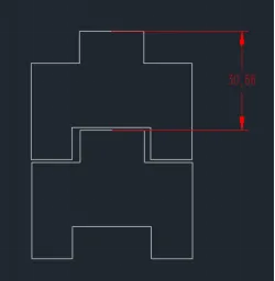
Reasonable design of sheet metal shape can effectively improve the utilization of sheet metal material.
2.Avoid the problem of material interference after sheet metal unfolding, try to bend and form at once
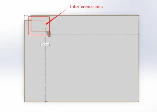
As in the following example, after the workpiece is unfolded, the two bending edges interfere with each other, and if they are cut directly without any modification, the interfering areas will be cut together, resulting in missing features in the overlapping parts;
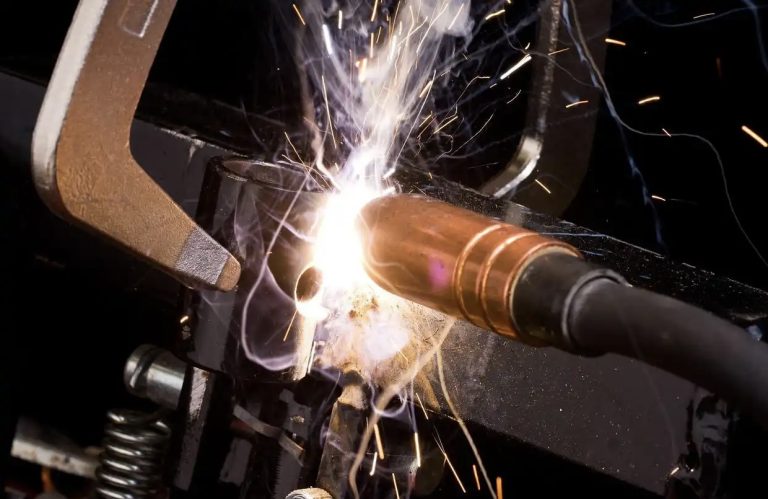
Generally in this case, we will split one of the sides first, and then after the bending is completed, we will weld the split side on.
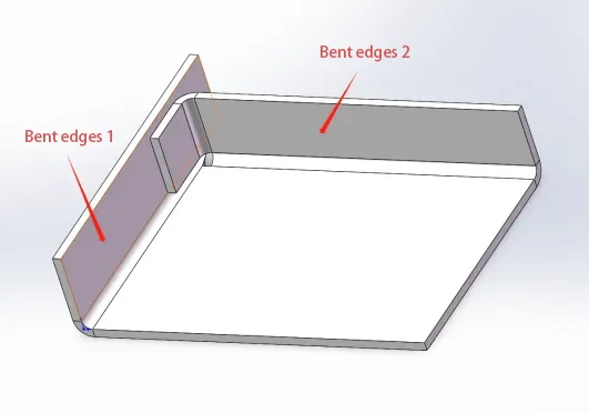
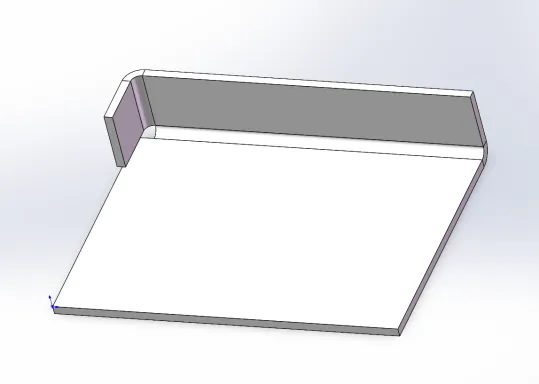
Remove one of the bending edges (Bending Edge 1), bend the part shown in the illustration and then weld the removed bending edge (Bending Edge 1) to the workpiece.
However, welding connects two plates into one through post-processing, while bending is processed on the same plate; therefore, the tensile and force strength of welding, as well as the aesthetics of the workpiece are not as good as direct bending, which means that the welded part may break when the workpiece is pulled by external forces.
In addition, welding is one more process than direct bending, and the time cost and processing cost of workpiece production are greatly increased; therefore, our suggestion is to bend as much as possible without welding, to avoid this problem from the design.
3.Hot melt, burnt edge issues
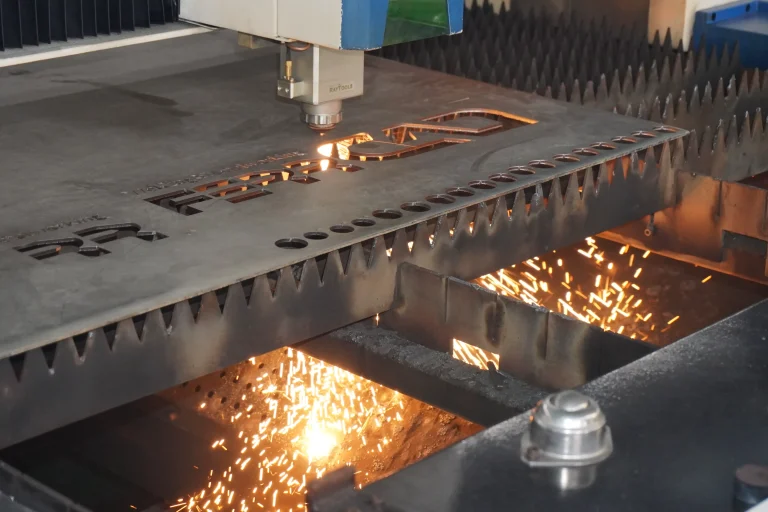
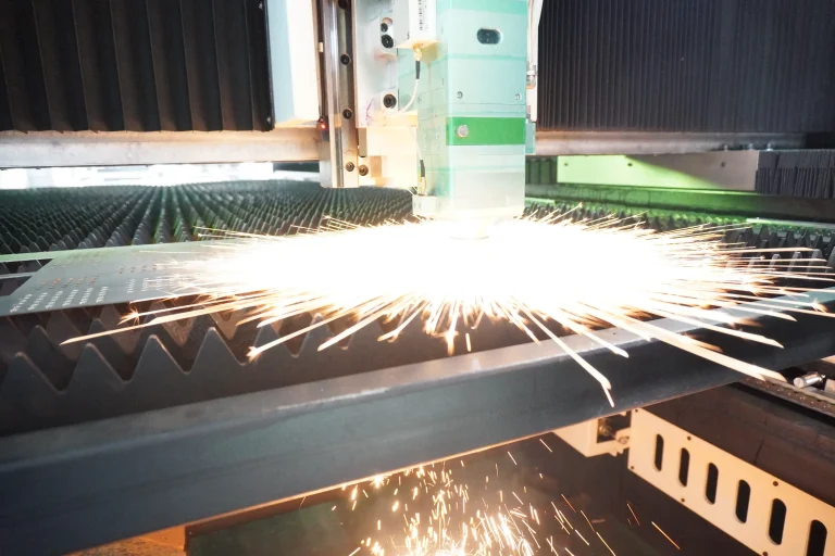
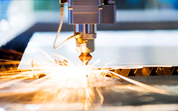
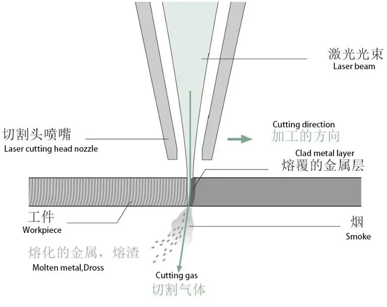
The principle of laser processing is that a high power density laser beam is directed onto the surface of the material and heats it up to thousands of degrees in a very short period of time, thus allowing the material to melt/gasify rapidly; at the same time, high-pressure gases are emitted from the side, blowing away the melted/gasified material and generating a slit in the plate, which ultimately serves the purpose of cutting the material.
The width of the slit will inevitably bring about the issue of the minimum cuttable kerf width, the minimum cuttable hole diameter and the minimum distance between the feature and the cutting edge. That is to say, we design how wide the groove, how big the hole, the edge and the edge of the distance between the reserved, in order not to be affected by the cut seam, to avoid the problem of thermal fusion burned edges, will want to be processed out of the features?
If there is a problem, we have to solve it, so we immediately did a lot of tests and got the following data for your reference:
(1)Minimum cuttable kerf width
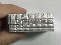
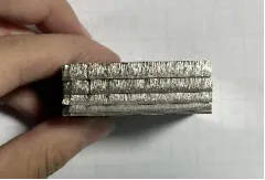
As shown in the figure, we drew a slit diagram, the first knife is a straight line, directly cut through; the second knife is a rectangle with a width of 0.01mm, i.e., the slit is 0.01mm; the third knife has a slit of 0.1mm; the fourth knife is 0.2mm; the fifth knife is 0.3mm; the sixth knife ……
The final result after laser processing is as follows (the picture is only for testing purposes, the appearance is not indicative):
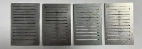
As you can see, the slit are cut out as expected, that is to say, no matter what material how big the plate thickness, the minimum cut width can reach 0.1mm or less.
Of course, the smaller the slit, the thicker the plate, the larger the slag; and because the aluminum material is soft, stainless steel and carbon steel material is hard, we also found in the processing of slag, the harder the material material, the harder the slag is difficult to deal with.
(2)Minimum Cuttable Hole Diameter
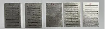
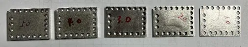
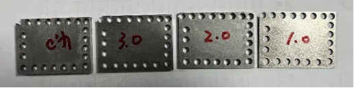
As with the test method for cut seams, we drew a graph of apertures with a minimum aperture of 0.25mm and a maximum aperture of 2.0mm.
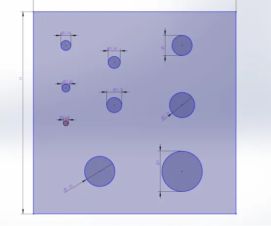
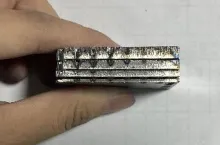
The following picture shows the final effect of the aluminum parts after laser processing (plate thickness from high to low, in order to retain the most realistic slag hanging situation, the workpiece in the following picture has not been treated in any way):
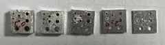
As you can see, as with the slit, the holes were cut out as expected, including the 0.25mm hole diameter! There is no case of not being able to cut through. And its cutting effect is the same as above: the smaller the slit, the thicker the plate, the greater the slag; the harder the material material, the more slag and more difficult to deal with.
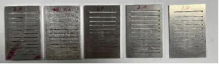
However, the role of the hole in the workpiece, in addition to the design of the aesthetic, but more of its purpose, there is a certain degree of accuracy required. Therefore, we have carefully observed some: (in order to retain the most realistic slag situation, the following picture of the workpiece has not done any processing)
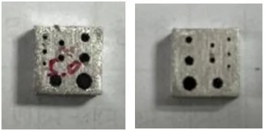
As shown in the figure is the front and back of the same workpiece, that is, the material plate thickness is the same; you can see that there is a difference between the front and back of the same workpiece aperture size, the front of the hole is the normal value, and turned to the reverse side, the hole becomes smaller! The thicker the plate, the smaller the hole, the greater the difference between the front and back hole size values.
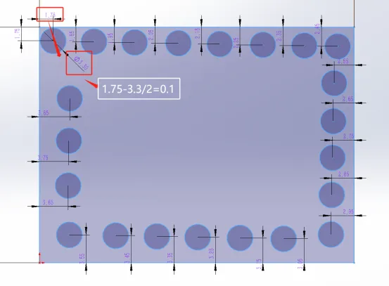
(3)Problem of minimum distance between feature and cutting edge
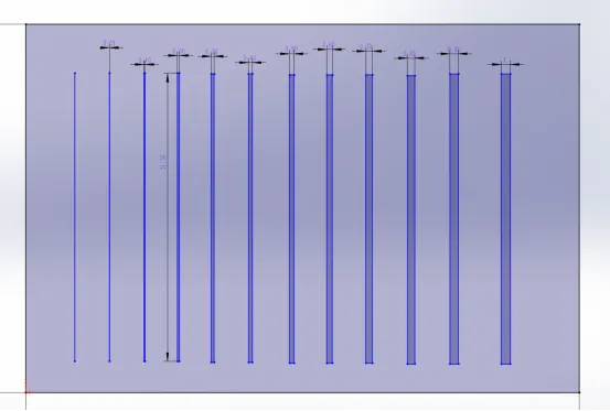
As shown in the figure, we have drawn a graph with a circular hole as a feature and the distance from the edge of the hole to the outer cutting edge as a variable, with the distance incrementing from 0.1mm, 0.2mm, 0.3mm to 2.2mm.
The final result after laser processing is as follows (the picture is only for testing purposes, the appearance is not indicative):

It can be seen that the aluminum burnt edge situation is the most detailed, carbon steel followed by stainless steel burnt edge situation is the weakest; that is to say, the softer the plate material, the greater the distance between the required features, the features can not be too close to the edge; and the thicker the thickness of the plate, the burnt edge of the situation is also more explicit, on the features and features, features and edges between the distance between the features and edges of the more far away.
And when we are drawing, the features to the edge of the distance set how much, in order to avoid the emergence of burnt edges, we this side of the simple to organize the data for your reference:
| Material | Thickness (mm) | Minimum Distance Between Features/Cutting Edge Without Burn Marks (mm) | Minimum Distance Between Features/Cutting Edge Without Deformation (mm) |
|---|---|---|---|
| Aluminum | 1.0 | 0.3 | 0.5 |
| 2.0 | 0.3 | 0.6 | |
| 3.0 | 0.5 | 0.8 | |
| 4.0 | 0.5 | 0.8 | |
| 5.0 | 0.6 | 0.9 | |
| Carbon Steel | 1.0 | 0.3 | 0.5 |
| 2.0 | 0.2 | 0.4 | |
| 3.0 | 0.4 | 0.6 | |
| 4.0 | 0.5 | 0.6 | |
| Stainless Steel | 1.0 | 0.2 | 0.3 |
| 2.0 | 0.3 | 0.4 | |
| 3.0 | 0.3 | 0.4 | |
| 4.0 | 0.3 | 0.4 | |
| 5.0 | 0.3 | 0.4 |
4.Thermal deformation problems
Laser processing, high heat input will lead to thermal deformation of the plate, the internal stress of the material will also be affected by the increase. We can unashamedly say that the laser processing of thermal deformation of the material is currently affecting the quality of the metal laser cutting machine processing a major problem, and the current industry application of technology, thermal deformation is difficult to solve the problem from the production chain. However, we can start from the design, by changing the design to avoid the problem of thermal deformation.
How to avoid the appearance of thermal deformation from the design? Below is a list of several common structural features that can easily lead to deformation, I do not know if there is any better way to solve the problem, welcome to leave a message in the comments section to discuss:
Long narrow strip structure:
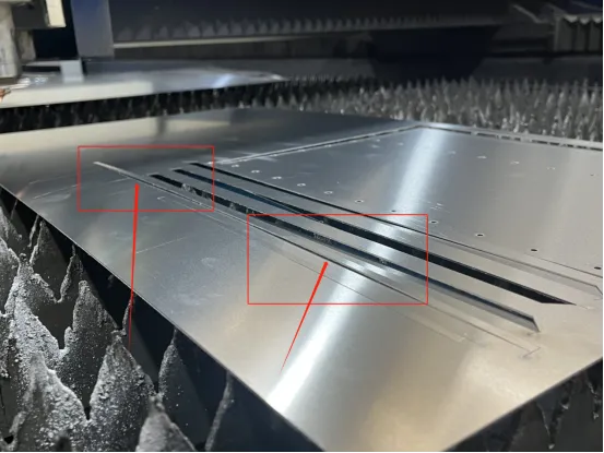
As shown in the picture above, the horizontal bar in the center is thin and long, which can easily cause the long narrow bar in the center to warp and distort. Generally speaking, our suggestion is to improve the structure by widening the distance gap between the long and narrow bars, or increasing the width of the long bars.
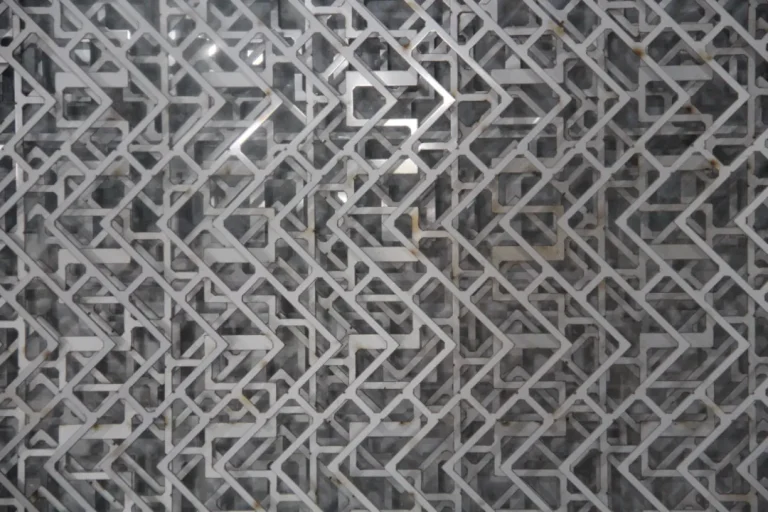
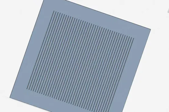
Feature-intensive structures:
Due to the denser arrangement of features, it leads to release of stress and heat deformation after cutting. Generally, workpieces with this feature structure are more suitable for press molding.
Thin plate materials are easy to be deformed:
Choosing the right material and plate thickness is also the key to solving the deformation problem of laser cutting thin plate materials. Different materials have different degrees of thermal conductivity and thermal expansion, which have different effects on laser cutting. Selecting materials with high thermal conductivity and low coefficient of thermal expansion can reduce the impact of thermal deformation during the cutting process. That is to say, when the workpiece is found to be deformed seriously during the workpiece processing, we can try to change the material and plate thickness to solve the problem.
If we encounter workpieces with frequent plate deformation problems, we should solve the problem from the design aspect. When designing the structure, we should try to avoid problems such as long and narrow strip structure and overly dense features.
design Design General Conclusion
- Designing a sheet metal part shape that is conducive to nesting can greatly enhance the utilization of sheet metal and reduce the generation of scrap, thereby reducing the cost of sheet metal materials.
- On the premise of not changing the use function of the product, try to make the workpiece bending and molding at one time by changing the design.
- Reasonably set the spacing of workpiece features to avoid thermal fusion and thermal deformation situations.
In conclusion, through reasonable design optimization, not only can plate utilization be improved and waste reduced, but thermal deformation and other issues during the processing of workpieces can also be avoided, thereby significantly reducing production costs. We hope this article provides valuable insights for you.